Running ESPHome on M5Stack Tab5 finally gives makers a tablet-class, wall-mountable ESP32-P4 touchscreen that speaks fluent Home Assistant. In this guide I show how to bring up the Tab5’s ESP32-C6 hosted Wi-Fi over SDIO (esp32_hosted), drive the 1280×720 MIPI-DSI display with LVGL and GT911 touch, and wire up ES8388/ES7210 audio for a local voice assistant. We’ll walk through power rails via PI4IOE5V6408, battery telemetry with INA226, practical performance tips for a 720p UI, and a flash-ready YAML. If you want a fast, reliable smart-home dashboard, HMI, or portable environment panel built on modern ESP32-P4 silicon, this is the deep-dive you’ve been waiting for.
Table of Contents
Overview & Why ESPHome on M5Stack Tab5

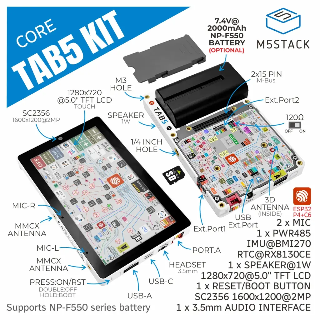
The M5Stack Tab5 is a 5″ 1280×720 IPS touchscreen panel built around Espressif’s ESP32‑P4 (dual‑core RISC‑V) with a companion ESP32‑C6 that provides Wi‑Fi 6 (& 802.15.4 radio on silicon).
It packs a bright display, GT911 capacitive touch, battery & charger, audio codec + dual mics, a ton of I/O (USB‑A host, RS‑485, expansion headers), and a neat enclosure. In short: it’s a tablet‑class HMI you can mount on a wall or deploy on a bench.
ESPHome now supports the Tab5’s architecture: the P4 runs your app and UI, while the C6 is attached by SDIO (configured via esp32_hosted:) to deliver Wi‑Fi. With LVGL embedded in ESPHome, you can ship a native, buttery‑smooth GUI without a browser. This guide captures the exact pieces that made our panel work reliably and then gives you a sanitized YAML you can flash immediately.
Heads‑up. This device is new, the P4 toolchain is evolving, and some features are still “early”. Expect fast improvements & keep your ESPHome version current.
M5Stack Tab5 Hardware Specs
| Subsystem | Details |
|---|---|
| MCU | ESP32‑P4 (dual‑core RISC‑V, ~400 MHz), 16 MB flash, 32 MB PSRAM |
| Wireless | ESP32‑C6 module (Wi‑Fi 6, 2.4 GHz; 802.15.4 on silicon). SDIO‑attached “hosted” to the P4. Internal/external antenna select. |
| Display | 5.0″ IPS, 1280×720 (MIPI‑DSI). PWM backlight on GPIO 22. |
| Touch | GT911 capacitive (I²C, IRQ & reset via expander). |
| Audio | ES8388 DAC/HP amp (speaker + 3.5 mm), ES7210 dual‑mic ADC for voice. |
| Power | Battery supported (INA226 for V/I), quick‑charge, multiple 5 V rails controllable via PI4IOE5V6408 expanders. |
| I/O | USB‑C (device), USB‑A (host), RS‑485, M5Bus/GROVE, GPIO header, microSD. |
| Form factor | Panel enclosure with kick‑stand; wall‑mount friendly. |
Setting Up ESPHome for the ESP32‑P4 + ESP32‑C6 (SDIO “hosted” Wi‑Fi)
The P4 has no radio. Wi‑Fi comes from the C6 via SDIO. In ESPHome, that link is enabled by esp32_hosted:. You must use ESP‑IDF (Arduino core is not available for P4) and, at the time of writing, enable experimental IDF features.
esp32:
  board: esp32-p4-evboard
  flash_size: 16MB
  framework:
    type: esp-idf
    advanced:
      enable_idf_experimental_features: true

esp32_hosted:
  variant: esp32c6
  active_high: true
  clk_pin: GPIO12
  cmd_pin: GPIO13
  d0_pin: GPIO11
  d1_pin: GPIO10
  d2_pin: GPIO9
  d3_pin: GPIO8
  reset_pin: GPIO15
  slot: 1
Power rails and peripherals are switched by two PI4IOE5V6408 I/O expanders. Define them on I²C and expose the rails you’ll need (USB 5V, external 5V, speaker amp, Wi‑Fi power/antenna, etc.). Turn on essentials in on_boot: so your screen and network come up deterministically.
Tip. Use
logger: hardware_uart: USB_SERIAL_JTAGfor first flash. It “just works” over the Tab5’s USB‑C.
Display, Touch & LVGL: How we got it working
ESPHome ships a dedicated mipi_dsi display driver for the Tab5. Backlight is LEDC‑PWM on GPIO 22. LVGL binds to that display and you get the full widget toolkit. Touch is GT911.
display:
  - platform: mipi_dsi
    id: tab5_display
    model: M5Stack-Tab5
    width: 720
    height: 1280
    reset_pin:
      pi4ioe5v6408: io_exp1
      number: 4

touchscreen:
  - platform: gt911
    id: touch_panel
    irq_pin: GPIO23
    reset_pin:
      pi4ioe5v6408: io_exp1
      number: 5

output:
  - platform: ledc
    id: backlight_pwm
    pin: GPIO22
    frequency: 1000Hz

light:
  - platform: monochromatic
    id: backlight
    output: backlight_pwm
For a polished look, include a PNG/JPG background and layer widgets above it.
Audio & Voice Assistant (ES8388 + ES7210)
The codec/ADC pair works with ESPHome’s i2s_audio, audio_dac, microphone, media_player, and voice_assistant primitives. It’s powerful but note that the pipeline is half‑duplex on P4 right now (listen or play, not both). For a minimal “panel‑first” build, you can add audio later.
Battery & Power Management Tips
- Expose
ina226for voltage/current; positive current generally indicates discharge, negative is charging. - Decide which 5 V rails you need at boot. Keep
wifi_powerON; toggle USB/external 5 V to save heat. - Quick charge control is inverted in hardware; the example sets sane defaults.
Known Limitations & Pro Tips
- Camera (MIPI‑CSI) not supported in ESPHome yet.
- Zigbee/Thread on the C6 isn’t exposed by ESPHome; treat the C6 as Wi‑Fi for now.
- P4 support in IDF/ESPHome is evolving; keep your toolchains updated.
- Prefer PSRAM‑friendly assets (RGB565 images, font subsets). 720p UIs are fast on P4 but still benefit from sane buffer sizes.

Boilerplate YAML for ESPHome on M5Stack Tab5 (flash‑ready, All core H/w included)
Copy the YAML below into ESPHome, update Wi‑Fi, and flash via USB. This version intentionally is an ideal boilerplate for M5Stack Tab5 on ESPHome:
esphome:
  name: tab5_panel
  friendly_name: "M5Stack Tab5 Panel"
  comment: "ESPHome config for M5Stack Tab5 - basic UI demo"
  on_boot:
    then:
      - switch.turn_on: wifi_power
      - switch.turn_on: usb_5v_power
      - switch.turn_on: external_5v_power
      - light.turn_on:
          id: backlight
          brightness: 100%

esp32:
  board: esp32-p4-evboard
  flash_size: 16MB
  framework:
    type: esp-idf
    advanced:
      enable_idf_experimental_features: true

esp32_hosted:
  variant: esp32c6
  active_high: true
  clk_pin: GPIO12
  cmd_pin: GPIO13
  d0_pin: GPIO11
  d1_pin: GPIO10
  d2_pin: GPIO9
  d3_pin: GPIO8
  reset_pin: GPIO15
  slot: 1

wifi:
  ssid: "YOUR_WIFI_SSID"
  password: "YOUR_WIFI_PASSWORD"

logger:
  hardware_uart: USB_SERIAL_JTAG
  level: INFO

ota:
  platform: esphome

api:

i2c:
  - id: bsp_i2c
    sda: GPIO31
    scl: GPIO32
    frequency: 400kHz

pi4ioe5v6408:
  - id: io_exp1
    address: 0x43
  - id: io_exp2
    address: 0x44

# Power rail controls
switch:
  - platform: gpio
    id: wifi_power
    name: "WiFi Power"
    pin: { pi4ioe5v6408: io_exp2, number: 0 }
    restore_mode: ALWAYS_ON

  - platform: gpio
    id: usb_5v_power
    name: "USB 5V Output"
    pin: { pi4ioe5v6408: io_exp2, number: 3 }
    restore_mode: RESTORE_DEFAULT_OFF

  - platform: gpio
    id: quick_charge
    name: "Quick Charge Mode"
    pin: { pi4ioe5v6408: io_exp2, number: 5, inverted: true }
    restore_mode: ALWAYS_ON

  - platform: gpio
    id: charge_enable
    name: "Battery Charging Enable"
    pin: { pi4ioe5v6408: io_exp2, number: 7 }
    restore_mode: ALWAYS_ON

  - platform: gpio
    id: wifi_antenna_int_ext
    name: "WiFi Antenna Switch"
    pin: { pi4ioe5v6408: io_exp1, number: 0 }
    restore_mode: ALWAYS_OFF   # OFF = internal antenna

  - platform: gpio
    id: speaker_enable
    name: "Speaker Amp Enable"
    pin: { pi4ioe5v6408: io_exp1, number: 1 }
    restore_mode: ALWAYS_ON

  - platform: gpio
    id: external_5v_power
    name: "External 5V Enable"
    pin: { pi4ioe5v6408: io_exp1, number: 2 }
    restore_mode: RESTORE_DEFAULT_OFF

# Optional: charge/headphone signals (can be kept or removed)
binary_sensor:
  - platform: gpio
    id: charging
    name: "Battery Charging"
    pin: { pi4ioe5v6408: io_exp2, number: 6, mode: INPUT_PULLDOWN }
    device_class: power

  - platform: gpio
    id: headphone_detect
    name: "Headphone Plugged In"
    pin: { pi4ioe5v6408: io_exp1, number: 7 }
    device_class: plug

# Optional: battery telemetry (no HA required)
sensor:
  - platform: ina226
    address: 0x41
    shunt_resistance: 0.005 ohm
    max_current: 8.192A
    bus_voltage:
      name: "Battery Voltage"
      unit_of_measurement: "V"
      accuracy_decimals: 2
    current:
      name: "Battery Current"
      unit_of_measurement: "A"
      accuracy_decimals: 3

time:
  - platform: sntp
    id: sntp_time

# Touch
touchscreen:
  - platform: gt911
    id: touch_panel
    irq_pin: GPIO23
    reset_pin: { pi4ioe5v6408: io_exp1, number: 5 }
    i2c_id: bsp_i2c

# Display (portrait 720x1280)
display:
  - platform: mipi_dsi
    model: M5Stack-Tab5
    id: tab5_display
    width: 720
    height: 1280
    reset_pin: { pi4ioe5v6408: io_exp1, number: 4 }
    # show_test_card: true

# Backlight
output:
  - platform: ledc
    id: backlight_pwm
    pin: GPIO22
    frequency: 1000 Hz

light:
  - platform: monochromatic
    id: backlight
    output: backlight_pwm
    restore_mode: ALWAYS_ON
    default_transition_length: 0ms

# LVGL and assets
lvgl:
  displays: [tab5_display]
  byte_order: little_endian

  top_layer:
    pages:
    - id: home_page
      bg_opa: TRANSP
      widgets:
        - image: { src: bg_image, align: CENTER }
        - label:
            id: lbl_time
            text: "00:00"
            align: TOP_MID
            y: 20
        - label:
            id: lbl_date
            text: "01/01/25"
            align: TOP_MID
            y: 60
Notes: Place your fonts and image files in the ESPHome project folder as referenced. If you prefer PNG, keep it; ESPHome converts to RGB565 internally based on type: rgb565. The minimal time/date labels are placeholders, you can bind them to SNTP values via a small script if desired.
5 Project Ideas to Build Next
- Wall‑mounted Smart‑Home Panel: LVGL dashboard for rooms, scenes, presence; voice wake to run automations.
- Portable Air‑Quality Station: Attach PM/TVOC/CO₂ via GROVE; live graphs on canvas; battery for surveys.
- Bedside Voice Assistant Clock: Big clock face + alarms + Assist; touch or voice to snooze/stop.
- Modbus HMI: RS‑485 to read/write registers on meters/PLCs; operator buttons on LVGL pages.
- IoT Teaching Rig: Multi‑page demo: GPIO, sensors, charts, simple robotics control, all in one box.
Wrap‑Up
The Tab5 + ESPHome combo gives you a modern embedded HMI: native graphics, solid Wi‑Fi, rich I/O, battery, and voice. Start with the sanitized YAML here, then layer in sensors, audio, and more pages as your use‑case evolves.


